Background
This course was called mechatronics and I completed 11 different labs as well as a two part project with 1 partner. The labs dealt with applications of sensors, microcontrollers, mobile robots and PLCs.
The objective of the course was to extend a student's working knowledge of engineering to include applied electronics and microcontroller programming, as well as to introduce issues that impact on the design of mechatronic systems.
Click here to learn more about the course.
The Project
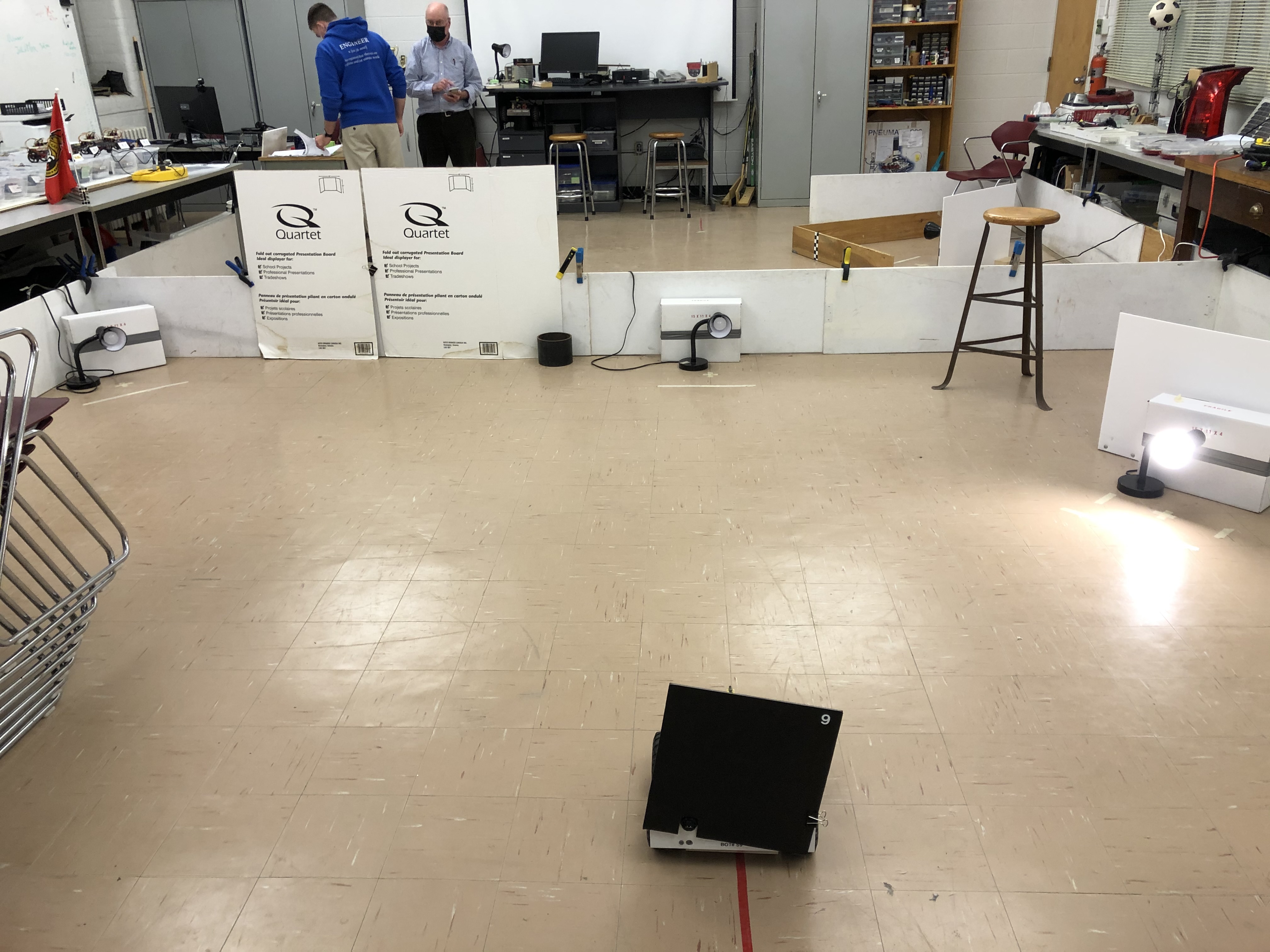
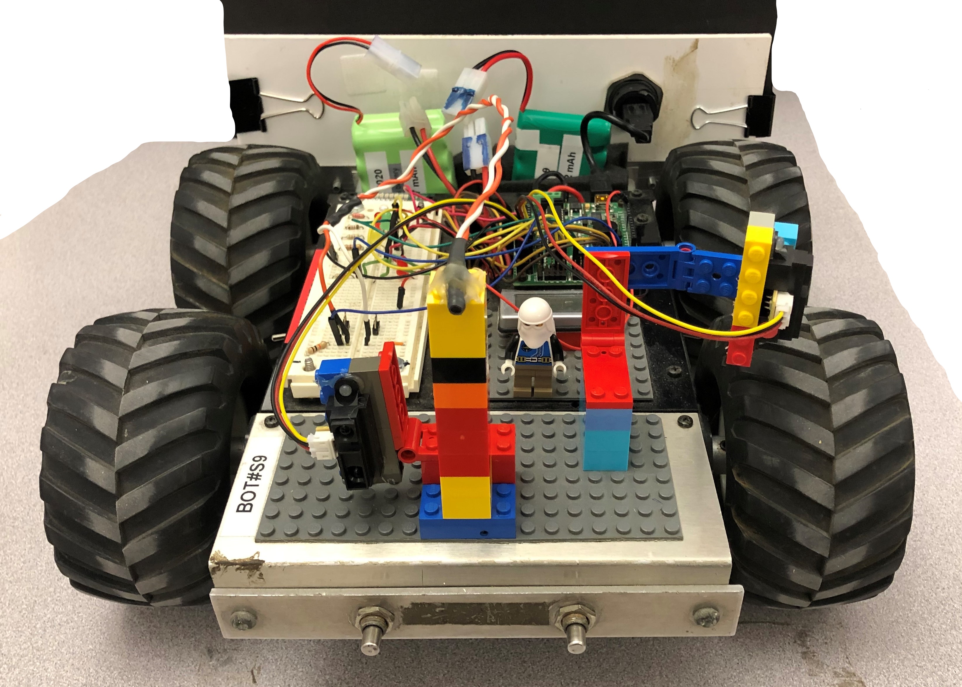
While there were many labs I am just going to focus on the main project for this course: to design a program that allows a given robot to navigate around a hallway and turn into a classroom where it then detects, drives towards and covers a light source. The robot setup used to accomplish the task as well as the main part of the test track can be seen in the images at the bottom of the page. Additionally, there is a video of my robot completing a perfect run for phase 1 of the project.
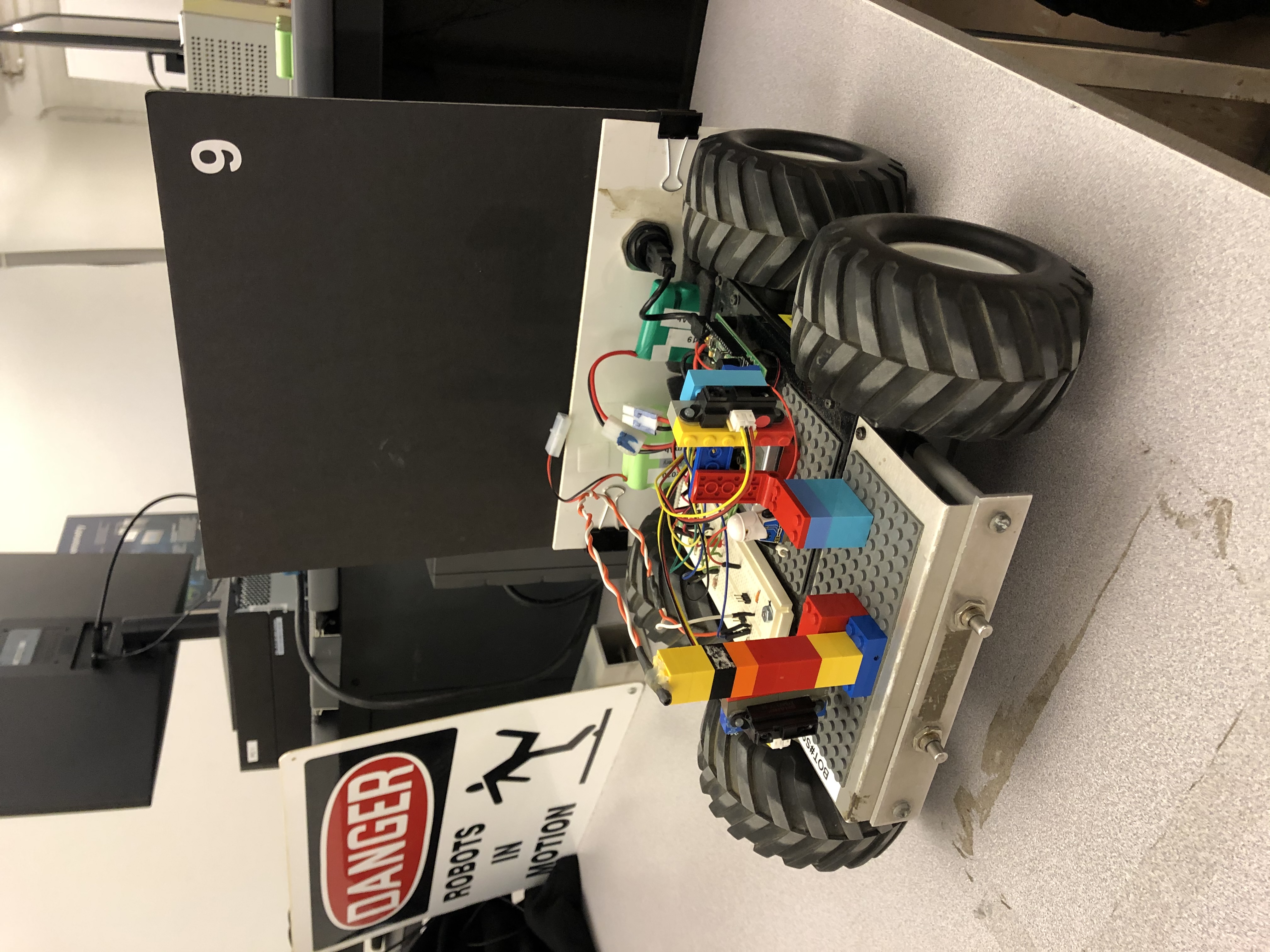
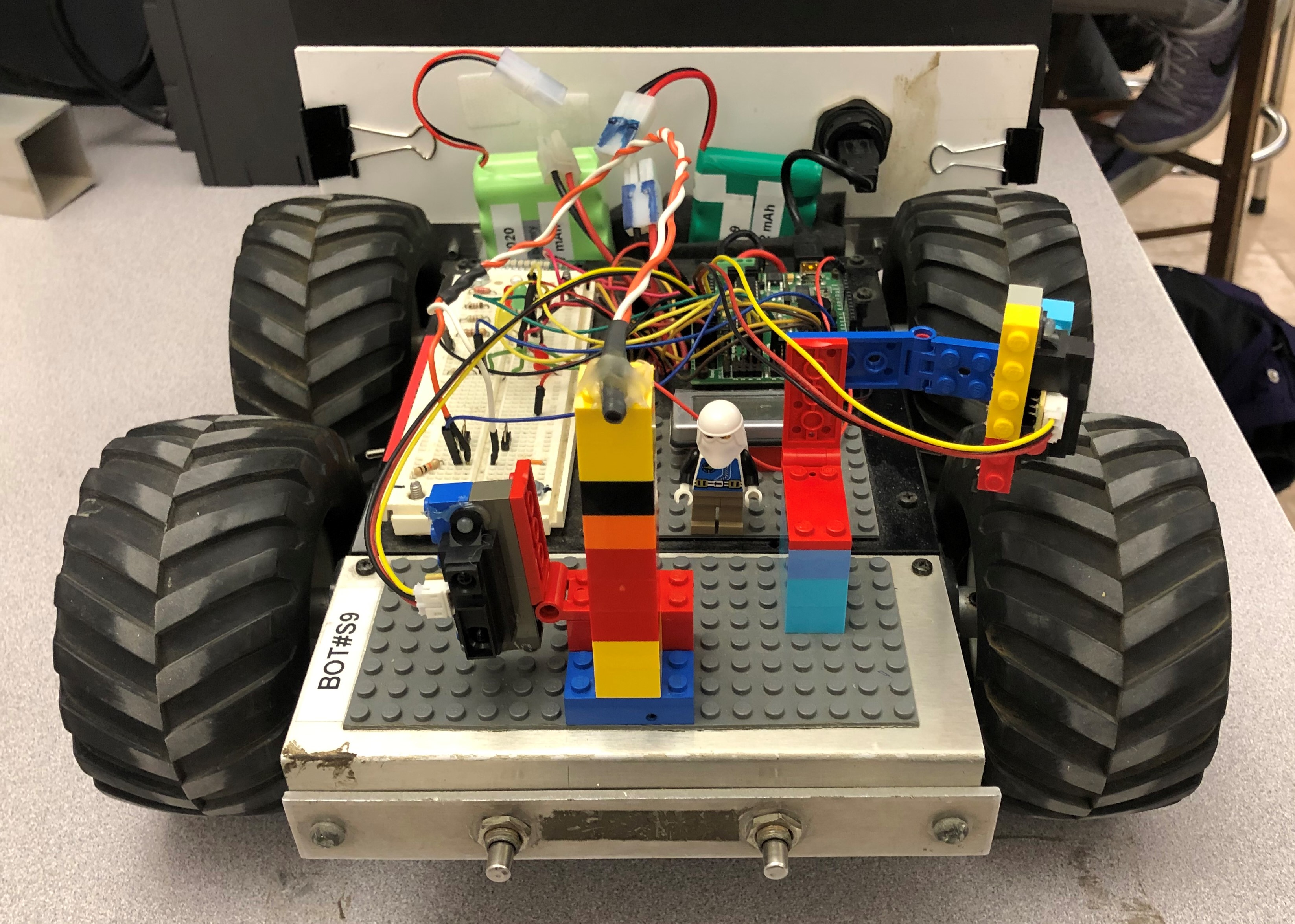
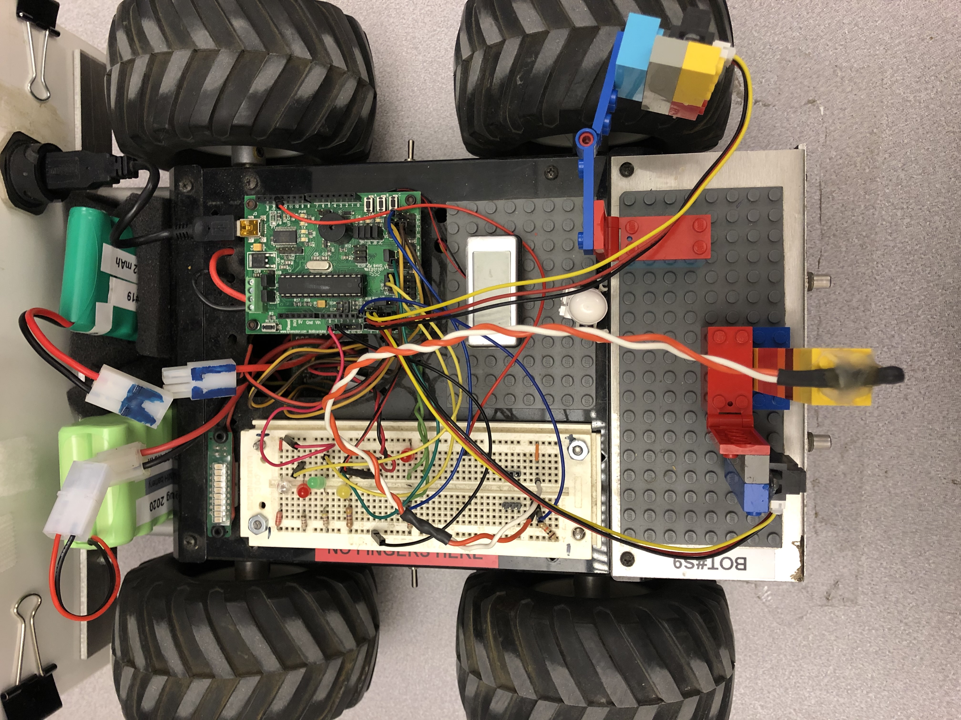
My partner and I received a perfect score during testing by using three sensors: a side-facing sharp, a front-facing sharp, and a front facing photoresistor. The left-side-facing sharp was used for wall following when entering the room, while the front-facing sharp was used to make a right when entering the room. The photoresistor was used to search for the light and to stop the robot when it got close enough to the light.
The Program
The program starts with the green LED flashing until the button is pressed which commences the wall following segment. During the wall following segment, the LynxBot completes two turns and then drives along the final straight-away until it reaches the sweeping area. Here, it completes a 180 degree sweep in order to locate the position of illuminated lamp. If lamp is four metres away, the LynxBot would rotate a fixed amount to improve its bearing to the lamp and would drive forward in order to complete its position correction sequence at a closer distance so that it is more accurate. It would then keep driving forward until the photoresistor detects a high enough brightness, or three seconds have passed. The code is then the same between the main branch and this offset branch which is why it connects back to the main segment in the flowchart. If the illuminated lamp was not detected to be the four metre lamp, the position correction sequence is completed. The LynxBot then advances forward until either the brightness level is high enough to indicate that the robot is close enough to complete the second sweep, or after two seconds have passed. At this point the LynxBot completes its sweep to improve its bearing and then it begins its bearing or position correction sequence in case the sweep was slightly off. After this, the LynxBot continues to advance forward until either the brightness is high enough to indicate that it is at the final location, or once the sharp detects that the LynxBot is close to the box behind the lamp. Once this is achieved, the LynxBot will pause for 2 seconds, turn 180 degrees counterclockwise, and move backwards for 0.5 seconds to block the light. The program will end after this point.
Click here to view the full phase 1 report for this project.
Video Demonstration
Figure Descriptions
Figure 1: LynxBot isometric view.
Figure 2: LynxBot front view.
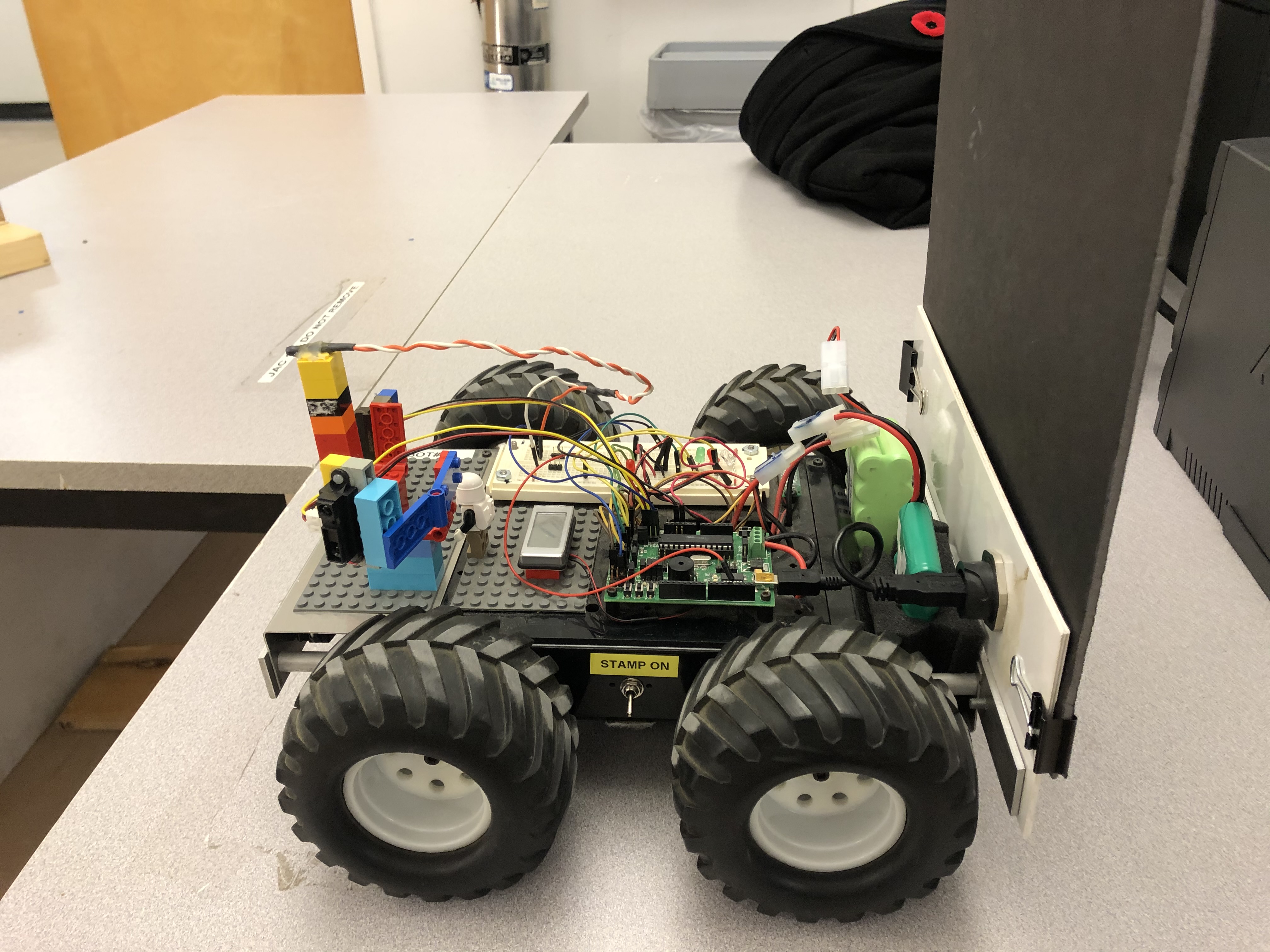
Figure 3: LynxBot side view.
Figure 4: LynxBot top view.
Figure 5: Layout of the testing area.